
International Space Elevator Consortium
October 2026 Newsletter
In this Issue:
President’s Note
Chief Architect’s Corner
The IAA’s Permanent Committee on Space Elevators
International Astronautical Congress 2026
Tether Materials
ISEC Terminology
Climber Motion Update
Around the Web
Upcoming Events
Contact Us
President’s Note
by Dennis Wright
ISEC 2026
From conference to conference, space elevator talks are getting increased visibility. As I reported in my last note, ISDC 2026 in June featured two space elevator sessions, one technical and another more general. In September, we had our two-day ISEC 2026 conference, with talks ranging from high-level concepts for space elevator usage to technical talks on the progress of various development projects. As in the previous two years, this conference was virtual. It was also very popular. More than 100 people registered for the first day and nearly that many for the second day.
In case you couldn’t attend, this is what you missed: “Comparing Space Elevators to Rockets: Cost and Environment”, “Technology and Missions for Space Elevator Spaceports”, “Laser Power Beaming to Climbers on the Space Elevator”, “New Methods of Large-Scale Graphene Production”, “Carbon Nano-threads as Potential Tether Materials”, “Updates on the Lunar Space Elevator”, and the list goes on. But don’t feel too bad...videos of the talks are available on the front page of the ISEC website https://www.isec.org/2026-isec-conference-videos. And if you love space elevator details, there will again be a volume of conference proceedings consisting of full write-ups of the presented talks. Even now, your friendly ISEC proceedings editor is collecting these papers and will publish them in January 2027. Access to these proceedings is free and will be available on the ISEC website.
I mentioned that this conference was virtual, but in the past, we have had many in-person conferences, mainly in Seattle and more recently in Chicago. Whether we go virtual or in person depends on finding someone to host and locally organize the event. Does this sound like something you’d like to do? It would be great to have a venue in another region of the country, or even internationally, as that’s what the “I” in ISEC stands for. Contact me: dennis.wright@isec.org.
Chief Architect’s Corner
by Pete Swan
The International Academy of Astronautics Supports Galactic Harbours
The International Academy of Astronautics (IAA) is Supportive of 9th Space Elevator Architectures – such as Logistics Giant Galactic Harbours.
The IAA has initiated a Permanent Committee on Space Elevators with a purpose of sharing proposed architectures within the global space community. We have seen growth from an initial concept in 1895, through science fiction and engineering estimates, leading to ISEC’s description of the Green Road to Space as the 8th architecture [Raitt, D. “Space Elevator Architectures,” Quest, Vol. 28, #1, 2021 pg. 17-26.]. The creation of the Academy Committee on Space Elevators will lead to several concepts and their benefits, maybe two or three 9th Architectures. We, in ISEC, are assisting in the development of various engineering and design concepts. In the April newsletter I stated: “The Academy purpose is to coordinate efforts in space elevator research and development projects across the globe and within national space agencies. The initial Academy efforts were to study the feasibility of space elevators and develop a 'way forward.' This was accomplished with publishing of two major research studies in 2013 and 2019.”
In the June newsletter I projected the term: “Logistics Giant”. My belief is that Modern-Day Space Elevators will become massive movers of logistics. The four main revolutionary strengths of full operational capabilities architecture (3 Galactic Harbours around the equator) are: (1) Mover of Massive Logistics to GEO, the Moon, and Mars at 170,000 tonnes per year, (2) Delivery Efficiency of 70% of mass at the Earth Spaceport to GEO, the Moon and Mars, (3) It will be the Green Road to Space as it does not burn rocket fuel in the atmosphere nor leave debris, and (4) As permanent space access infrastructures, the operations will be routine, daily, safe, inexpensive, and environmentally friendly.
Since the Academy Committee was formed, I have been leading the sub-committee on architecture and have come to the conclusion that this activity over the next 4 years can lead to a very specific 9th architecture. I am hoping the committee can support development of three different “looks” at the future. However, I am starting with my concept of a logistics giant as thrust to focus our development, leading to our intended Full Operational Capability architecture. Let us team with rockets to move people through the radiation belts rapidly while space elevators support the movement off planet with delivery of massive logistics. I call our new proposed 9th architecture Logistics Giant Galactic Harbours. This permanent infrastructure was presented at the British Interplanetary Society’s evening lecture (16 Sept 2026) and can be reviewed here: https://www.isec.org/s/British-Interplanetary-Society-Evening-Lecture-16-Sept-2026.pdf. I will try to keep everyone up to speed on where we are going and how close we are with notes in newsletters, presentations, and articles as appropriate; however, if you are interested in contributing – please contact me through info@isec.org.
The Permanent Committee on Space Elevators (PCSE)
at the International Academy of Astronautics (IAA)
The IAA leveraged the International Astronautical Congress (IAC) gathering in Turkey earlier this month to have two expansion events on space elevators. These were:
1 – Presentation at Academy Day: The Academy has a full day prior to the IAC each year and presents the top topics for general discussions across the global space arena. This year, the PCSE was asked to present a status report. We projected future activities leading to international assessments of space elevator development over the next several years. The committee structure has five sub-committees to distribute the focus upon “big items”. The image below is from the chair Mr. Tsuchida.
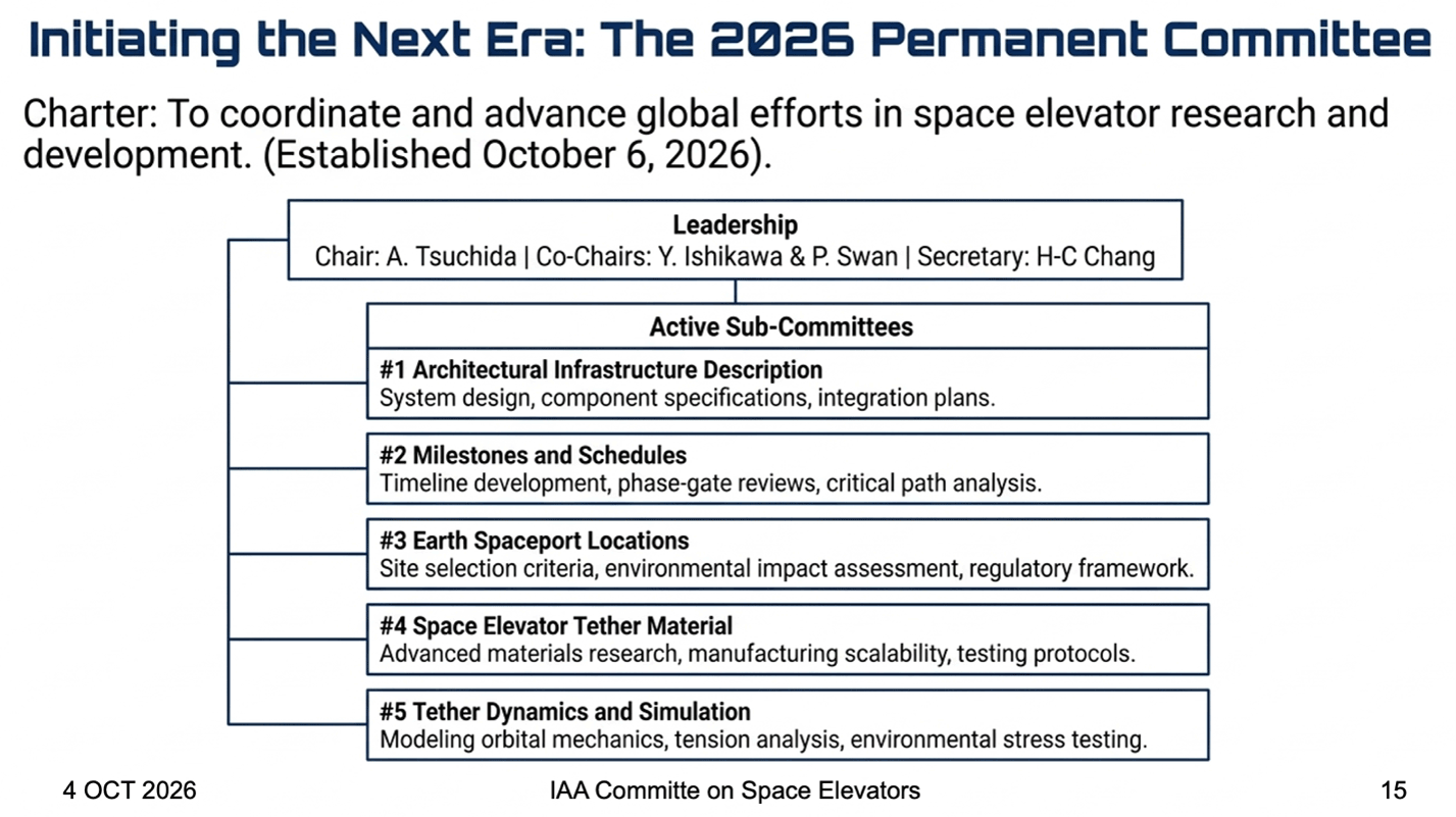
2 – In addition, on Tuesday of that week, the committee met and had their preliminary discussions introducing the players and thinking about how to initiate this large – global – megaproject. Each of the sub-committees presented their preliminary ideas. There is a site on LinkedIn providing updates and plans for the permanent committee and its many sub-committees. If you are interested in joining an active sub-committee, please send your information to info@isec.org and we will coordinate your interests.
International Astronautical Congress 2026
by John Knapman
The International Astronautical Congress (IAC) was held in Antalya, Turkey, in early October 2026. On October 4th, before the main sessions, Akira Tsuchida presented the merits of space elevators to the International Academy of Astronautics (IAA) meeting, and he outlined the working of the newly established IAA Committee on Space Elevators. There were several detailed questions, and the talk was well received. However, one later speaker did express his doubt about the need for space elevators.
On October 6th, we held the inaugural meeting of the IAA Committee and received reports from the five subcommittee chairs: Pete Swan (online) on Architecture, Yoji Ishikawa on Milestones and Schedules, Akira Tsuchida on Earth spaceport locations, Adrian Nixon on Tether Materials (delivered by John Knapman), and Dennis Wright (online) on Tether Dynamics and Simulation. There was a general air of optimism.
The same day, the space-elevator technical session took place. Before it started, we played the song “The Green Road to Space” by Dr. Donny “Rocker” Deever, but people kept interrupting it so that they could check their slides. Yoji Ishikawa gave the Jerome Pearson memorial lecture, talking about managing megaprojects and the fact that only 0.1% of such projects come in within budget and on time. John Knapman presented a paper by Pete Swan about spaceports along the tether for different purposes, such as launching to the Earth-Sun L1 Lagrange point. John also presented papers on solar-powered climbers and on defect tolerance in a tether. I think the best-written and best-presented paper was by Masashi Kamogawa about lightning and how to avoid it.
Oleh Babanin, an independent researcher from Ukraine, presented a new idea for lifting payloads from Earth to an orbiting satellite, which would be 5,000 km long with a mass of 800,000 tonnes. Phil Swan spoke about electromagnetic space launch at a session on Future Space Transportation Systems. Ravin Phetcharatana is an interesting contact. He has secured funding for a company of seven people in Bangkok to build a small-scale space elevator. He particularly praises Blaise Gassend for his insights.
The closest hotel to the conference center was a beach resort which had pleasant gardens and agreeable restaurants where we could dine under the stars. Next year the IAC will be held in Poznań, Poland. In two years’ time it will be in Samarkand, Uzbekistan, a city on the ancient Silk Road, which was a trading route that connected China to Europe.
Photos of the event can be found on our Flickr page https://flic.kr/s/aHBqjD6Nh7.
Tether Materials
by Adrian Nixon
The Tensile Strength of Polycrystalline Graphene
Dear Reader, as part of the preparation for this year’s ISEC conference, I created a table that summarised the key properties of the leading carbon-based tether materials including diamond nanothreads and nanotubes. Polycrystalline graphene came out at the top of the table with the stronger single crystal graphene a close second because it can already be manufactured in lengths of up to 1 kilometre.
I was challenged on the tensile strength of polycrystalline graphene because I had quoted a value of 90 to 99 GPa based on work done by Columbia University in the USA and Samsung in Korea (Lee 2013). This work found that well-stitched-together polycrystalline graphene was nearly as strong as single crystal graphene. My colleague, John Knapman, pointed out that a more recent paper, by an international team led by the Université Catholique de Louvain in Belgium (Jaddi 2024), found that grain boundary defects could reduce the strength of the graphene and a figure between 57 and 110 GPa was likely with a recommendation to quote the lower value.
We decided to take a broader look at the literature to find what other work had been done measuring the tensile strength of polycrystalline graphene. The search results are summarised in Table 1.
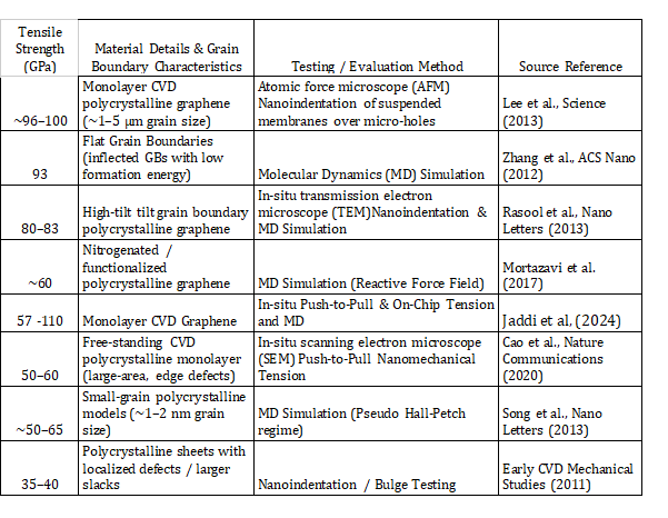
Table 1: Summary of available tensile testing results on polycrystalline graphene.
The results showed a range of values from 35 GPa up to 110 GPa. This is partly due to a combination of different test methods and computer simulation results. It is also due to a range of graphene sample qualities. As well as grain boundaries, small vacancy defects (missing carbon atoms) in the graphene can have a dramatic effect on the strength of the graphene sheet and vacancy defects are very hard to spot on macro level samples where the likelihood of incorporating sub-nanometre flaws increases dramatically.
There is another effect… the angle at which grain boundaries meet was discovered to be very important for the tensile strength measured (Rasool 2013). Where grain boundaries meet with a high angle, the material is stronger than material with low-angle boundaries. Large-angle boundaries reach a strength comparable to single-crystal graphene.
So, asking a simple question, “what is the tensile strength of polycrystalline graphene?” turns out to have an answer that is more complicated than we might have thought. There is a range of values generated by different test methods, computer simulations, and graphene samples.
For the moment, we are quoting measured tensile strengths in the range of 57 to 110 GPa. Perhaps we should not be surprised by the vague answer to a clear question. We are at the point where we are moving from laboratory-tested samples to industrially manufactured material and the material manufacturing and quality control test methods have not yet developed to a sufficiently mature level to provide the clear answers we need. In the spirit of many academic research papers – more work needs to be done. We will monitor and report on progress as the field develops and matures.
References
Cao, C., et al. (2020). Probing the ultimate strength of polycrystalline graphene. Nature Communications, 11, 2836.
Grantab, R., Shenoy, V. B., & Ruoff, R. S. (2010). High strength of polycrystalline graphene containing tilt grain boundaries. Science, 330(6006), 946–948.
Jaddi, S., Malik, M.W., Wang, B., Pugno, N.M., Zeng, Y., Coulombier, M., Raskin, J.-P. and Pardoen, T. (2024). Definitive engineering strength and fracture toughness of graphene through on-chip nanomechanics. Nature Communications, [online] 15(1). doi:10.1038/s41467-024-49426-3.
Lee, G.-H., et al. (2013). High-strength chemical-vapor–deposited graphene and grain boundaries. Science, 340(6136), 1073–1076.
Li, P., et al. (2020). Continuous crystalline graphene papers with gigapascal strength by intercalation modulated plasticization. Nature Communications, 11, 2758.
Mortazavi, B., Rahaman, O., Timon, R. and C., P.L.F. (2017). Thermal conductivity and mechanical properties of nitrogenated holey graphene. arXiv. doi:10.1016/j.carbon.2016.05.009.
Na, S. R., et al. (2016). Cracking of polycrystalline graphene on copper under tension. ACS Nano, 10(10), 9616–9625.
Rasool, H. I., et al. (2013). Continuity and strength of grain boundaries in chemical vapor deposited graphene. Nano Letters, 13(4), 1397–1403.
Ruiz-Vargas, C. S., et al. (2011). Softened elastic response and reduced fracture strength in polycrystalline graphene. Nano Letters, 11(6), 2259–2263.
Shekhawat, A., & Ritchie, R. O. (2016). Toughness and strength of nanocrystalline graphene. Nature Communications, 7, 10546.
Song, Z., Artyukhov, V.I., Yakobson, B.I. and Xu, Z. (2013). Pseudo hall–Petch strength reduction in polycrystalline graphene. Nano Letters, 13(4), pp.1829–1833. doi:10.1021/nl400542n.
Xiao, B., et al. (2023). Significant enhanced mechanical properties of suspended graphene film by stacking multilayer CVD graphene films. Micromachines, 14(4), 745.
Zhang, J., Zhao, J., & Lu, J. (2012). Intrinsic strength and failure behaviors of graphene grain boundaries. ACS Nano,6(3), 2704–2711. https://doi.org/10.1021/nn3001356
ISEC Terminology
by Pete Swan
“Delivery Efficiency 70%”
For the last ten years our estimates for the initial operational space elevator tether climbers have used a climber mass of 6 tonnes and payload mass of 14 tonnes. This means the released customer payload reaches its destination with 70% of the mass at liftoff on the pad. As such, the term delivery efficiency has surfaced to illustrate this transformational strength vs. rockets with their delivery efficiency of 2% to GEO and only 1% to lunar orbit (or Martian).
Climber Motion Update
by Peter Robinson
Part 3: Mass/Power Ratio
1. Introduction
This article follows on from articles in the August and September 2026 newsletters [1] [2] which explore how Earth Space Elevator climber power and speed will impact performance for a fixed tether capacity, based on methodology explained in my 2022 IAC paper [3] and prompted by the 2026 ISEC Study Report “Powering the Space Elevator” [4].
This third article now looks at another key parameter, the climber Mass/Power Ratio. My earlier work made the simplistic assumption that the climber unladen (tare) mass would be proportional to the drive power; there may be some non-linearity if (for example) component sizes vary instead of their number, but I will not attempt to estimate this.
The ISEC baseline design is a 6-tonne unladen climber with 4 MW drive power carrying 14 tonnes of payload [5]; this analysis will now assess how variation from this “baseline” 1.5 t/MW might impact key operational parameters.
At each condition the payload (net) mass is derived from the simple equations below:
Total (Gross) Mass = Unladen (Tare) Mass + Payload (Net) Mass [Equation 1]
where Tare Mass = Drive Power x Mass/Power Ratio [Equation 2]
Note: my analysis is based on a simple “static” system model, with no allowance for dynamic effects. It assumes a fixed climber drive power when the ascent speed is below some maximum value; when that speed is reached, the power reduces to limit the speed to the maximum. The maximum speed is usually reached in the first few thousand kilometres during the first two or three days of ascent as Earth’s gravity falls rapidly with altitude.
2. Effect of Mass/Power Ratio on Payload with Constant Tether Load
I will first present analysis for three values of Mass/Power Ratio at 235 km/hr, showing the change in gross and net masses as the power of the unladen climber varies. The gross mass is adjusted to hold the peak tether stress constant as the climber weights and distribution along the tether vary.
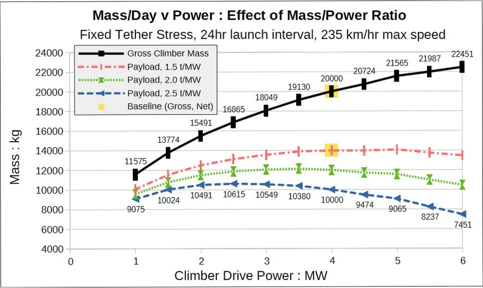
Figure 1: Daily Climber Mass (Gross & Net) v. Climber Drive Power v Tare Mass/Power Ratio, for 24-hour climbing at up to 235 km/hr, fixed tether load and daily departures. Analysis: P. Robinson.
The upper two lines on Figure 1 were included in the previous article and can be seen to pass through the baseline masses of 20,000 kg and 14,000 kg at 4 MW drive power. As discussed before, higher drive powers increase the possible gross climber mass but not necessarily the net payload.
The lower two lines show new data for higher Mass/Power Ratios, with results at 2.0 tonnes/MW and 2.5 tonnes/MW. The latter dataset (blue triangles) is of particular interest as it is close to the 10,622 kg / 4 MW "feasible design" discussed in the 2023 Climber-Tether Interface Study [5]. It can be seen that a lower drive power would enable more payload to be raised each day to GEO.
This conclusion may be counter-intuitive but arises from the large reduction in the tare mass and the need to maintain the same tether loading. Another perspective arises from considering efficiency: a more powerful climber will reach the speed limit sooner, meaning the extra drive-system mass is used for less time and is surplus for more of the ascent.
The previous article evaluated a maximum climber speed of 235 km/hr, required for an ascent time to GEO of 7 days, but concluded that a maximum speed of 160 km/hr (100 mph) might be a less challenging target for early climbers. Figure 2 below shows data from analysis repeated at this lower ascent speed limit.
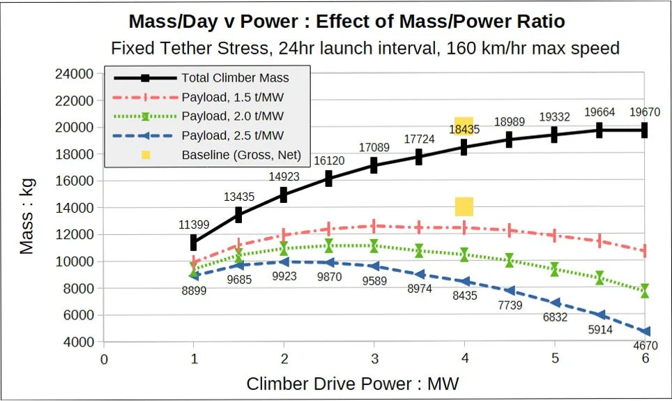
Figure 2: Daily Climber Mass (Gross & Net) v. Climber Drive Power v Tare Mass/Power Ratio, for 24-hour climbing at up to 160 km/hr, fixed tether load and daily departures. Analysis: P. Robinson.
This plot, with the same axis scales as Figure 1, shows how the need to maintain tether stress results in a lower gross climber mass at all powers, especially above 4 MW. Again, higher potential daily payloads can be achieved at lower drive powers.
One observation of interest is that at the "feasible design" Mass/Power Ratio of 2.5 t/MW, the 10,000 kg payload at 4 MW power & 235 km/hr can be almost achieved with only 2 MW power & 160 km/hr, the mass difference being only 77 kg (0.77%).
3. Effect of Mass/Power Ratio on Tether Load with Constant Payload
Unfortunately, the above strategy of holding the tether strength fixed moves the climber design away from the target of a 20-tonne climber raising 14 tonnes of payload each day. If the ideal maximum climb speed (235 km/hr) and mass/power ratio (1.5 t/MW) cannot be met, it might be decided to deploy a more massive tether to support heavier climbers and more closely approach the target performance.
Figure 3 below shows the total suspended weight of all the daily climbers between the Earth Port and GEO plotted against the maximum drive power, for maximum speeds of 235 and 160 km/hr. For each data point the payload is fixed at 14 tonnes and the gross climber mass is calculated based on the mass/power ratio (as Equations 1 & 2 above).
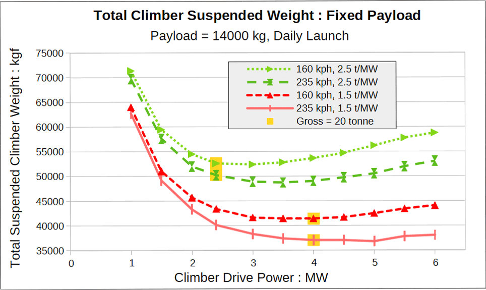
Figure 3: Total Climber Weight v. Climber Drive Power v Tare Mass/Power Ratio, for fixed Payload = 14 tonnes, 24-hour climbing at 160 km/hr & 235 km/hr, daily departures. Analysis: P. Robinson.
This plot includes data (yellow squares) for a gross climber mass of 20 tonnes, but these are for reference only and are not recommended match points. It can be seen that the 4 MW power is close to optimum for the “baseline” climber design (solid line), but lower powers would be better with a lower maximum speed and higher Mass/Power Ratio.
Note: I have assessed the total suspended weight of the climbers as this directly dictates the required strength of the tether. I have not plotted exact tether stress or tension as these depend on tether material properties, safety margins, Earth Port tension, and other factors, all of which are outside the scope of this article.
That said, the tether design within my model yields a stress increase of 11.3% for the 29.2% total weight increase at the worst-case 160 km/hr & 2.5 t/MW, requiring a tether mass increase of around 600 tonnes, but this is indicative only and will vary with other tether properties and designs. A simple calculation shows that such an additional tether mass (and a heavier Apex Anchor mass) would be offset in less than a year by the additional payload of 4 tonnes each day, but this is a matter for future economic and business case decisions.
4. Conclusions
+ The specific mass of the unladen climber, expressed as Mass/Power, is key to maximising the daily payload of any space elevator climber.
+ If the specific mass increases, the optimum climber drive power to maximise the daily payload-to-GEO will reduce below the 4 MW assumed in earlier concepts and design studies.
+ A business decision must determine the optimum tether mass for initial operations, based on engineering estimates of short-term and medium-term climber performance as well as predicted material properties and other factors.
The next article will address the climber launch frequency: assuming some power source that will enable continuous 24-hour-per-day climbing, is one launch each day the best solution?
5. References
[1] “Climber Motion Update: Power and Cost”, P. Robinson, August 2026 ISEC Newsletter Article.
[2] “Climber Motion Update: Part 2”, P. Robinson, September 2026 ISEC Newsletter Article.
[3] “Space Elevator Climber Dynamics Analysis and Climb Frequency Optimisation.”, P. Robinson, IAC 2022 paper IAC-22,D4,3,8,x68299.
[4] “Powering the Space Elevator”, L. Bartoszek et al., ISEC 2026 Study Report.
[5] “The Climber-Tether Interface of the Space Elevator”, D. Wright, L. Bartoszek et al., ISEC 2023 Study Report.
Around the Web
Mordy Friedman, founder/CEO of WSPEC, is among the NSS Inaugural 30 Under 30 honorees.
https://nss.org/meet-the-inaugural-nss-30-under-30-class-of-2026/
Upcoming Events:
See also https://www.isec.org/events
2026 International Symposium on the Peaceful Use of Space Technology—Health (IPSPACE)
Sponsored by the International Peace Alliance
https://spacetu.org.cn/
Monday, November 16th through Thursday, November 19th, 2026
Sanya, Hainan Province, China
WSPEC Japan 2026
Organized by WSPEC and Japan Space Elevator Association (JSEA)
https://www.wspec.org/events
https://jsea.jp/2876
Saturday, November 28th, through Sunday, November 29th, 2026
International Space Development Conference (ISDC) 2027
Sponsored by the National Space Society (NSS)
https://isdc.nss.org/
Thursday, May 27th through Sunday, May 30th, 2027
Sheraton Gateway Los Angeles, CA, USA
Theme: “At Home on the Moon”
78th International Astronautical Congress
Sponsored by the International Astronautical Federation (IAF)
https://www.isec.org/events/iac2027
Monday, September 27th through Friday, October 1st, 2027
Poznań, Poland
79th International Astronautical Congress
Sponsored by the International Astronautical Federation (IAF)
https://iac2028.com/
Monday, October 9th through Friday, October 13th, 2028
Samarkand, Uzbekistan
80th International Astronautical Congress
Sponsored by the International Astronautical Federation (IAF)
Monday, October 8th through Friday, October 12th, 2029
Geneva, Switzerland
Contact Us:
Our website is www.isec.org.
You can find us on Facebook, X, Flickr, LinkedIn, Instagram, YouTube, Bluesky and Reddit.
Support us:
Sign up to be a member at: https://www.isec.org/membership
You can also give directly using the “Donate” link at the bottom of our website page.
Does your place of employment do matching funds for donations or volunteer time through Benevity? If so, you can make ISEC your recipient. Our 501(c)(3) number is 80-0302896.