
International Space Elevator Consortium
September 2026 Newsletter
In this Issue:
Editor’s Note
Chief Architect’s Corner
Climber Motion Update Part 2
ISEC Terminology
Tether Materials
Musical Corner
Around the Web
Upcoming Events
Contact Us
Editor's Note
Dear Space Elevator Enthusiasts,
I have been remiss in congratulating new board members when they joined, and so, with apologies to those I previously failed to recognize, I would like to introduce two new members to the ISEC Board of Directors...welcome: Steven Griggs, Ph.D., and Charles Krone!
If you haven't already signed up for the Space Elevator Conference, you can still sign up during the conference and immediately receive a link to join us this weekend! Sign up here: https://www.isec.org/events/isec2026.
Sandee Schaeffer
Newsletter Editor
Chief Architect’s Corner
by Pete Swan
New Academy SE Committee
The International Academy of Astronautics has established a Committee on Space Elevators to coordinate efforts in space elevator research and development projects across the globe and within National Space Agencies. The current understanding of future capabilities of these mega-projects is wide ranging and must be stimulating enough to gain approval in order to move forward. Modern-Day Space Elevators will leapfrog the rocket equation and enable humanity to move off planet with a permanent, efficient, and transformational infrastructure. ISEC will contribute through its participation in the subcommittees and leveraging its broad Body of Knowledge. The subcommittee approach currently has five topics as initial study focus. Our ISEC leadership will be instrumental to the future refinement of “where we are and where we want to be.” They are:
I. Permanent Architecture Infrastructure Description (Peter Swan, Chair)
+ The description would identify major segments of Modern-Day Space Elevators and define how they would interface with other segments of the infrastructure.
II. Milestones & Schedule (Yoji Ishikawa, Chair)
+ Examine the milestones and schedule throughout the life cycle of space elevators and build consensus within the committee toward that timeline.
+ Identify issues at each life cycle/stage (Planning, technology development, design, construction, operation, and disposal)
+ The initial review period shall be two years
III. Location of Earth Spaceports (Akira Tsuchida, Chair)
+ Evaluate trade-offs regarding optimal Earth Spaceport locations. This analysis will consider the functional allocation required for future commercial Space Elevator utilization.
IV. Space Elevator Tether Material (Adrian Nixon, Chair)
+ Identify and Explain candidate tether materials such as polycrystalline graphene, single crystal carbon nanotube (CNT), single crystal graphene 2D materials, single crystal hexagonal boron nitride (hBN), and single crystal hexagonal boron nitride nanotubes (BNNT) 1D material.
V. Ribbon / Tether Dynamics (Dennis Wright, Chair)
+ Developing a Gold Standard for dynamics simulation of space elevator tethers.
There are many other members of ISEC participating and if one of the areas falls into your expertise and you wish to contribute, please contact Pete Swan at info@isec.org.
Climber Motion Update – Part 2
by Peter Robinson
Speed
1. Introduction
This article follows my article in the August 2026 newsletter [1] which explored the effect of an Earth Space Elevator climber power on payload mass and cost for a fixed tether capacity, based on methodology as explained in my 2022 IAC paper [2] and prompted by the recent ISEC Study Report “Powering the Space Elevator” [3].
This second article now looks at the impact of another key parameter, the maximum climber ascent speed. Again, my analysis is based on a simple “static” model, with no allowance for any dynamic effects.
2. Effect of Maximum Speed on Time to GEO
My model assumes that the climber drive power is constant when the ascent speed is below some maximum value; when that speed is reached, the power reduces to limit the speed to the maximum. The Earth’s gravity falls rapidly with altitude, meaning that the maximum speed is usually reached in the first few thousand kilometres during the first two or three days of ascent.
In the first article, I selected a maximum speed of 235 km/hr (147 mph) as that yielded a journey time to GEO of 7 days, but I consider this a highly optimistic target for a wheeled vehicle. The speed limit will be constrained primarily by two factors: steering and drive system limitations.
The steering may prove to be the most challenging, considering the width of the tether (1m or less), the mass of the climber, the low friction tether surface, and the inability to apply loads to the sides of the tether (it is far too thin). I won’t discuss details of potential steering mechanisms, but several have been proposed including wheel turning or twisting (as conventional vehicle steering), gyroscopic twisting, balance twisting, or even lateral electromagnetic forces.
The drive system limitations will be mainly associated with the rotating speed of the wheels and other drive components; these are more conventional in nature and so should be less difficult to resolve.
Whatever steering system is used, a maximum speed of 235 km/hr will not be easy, at least in early design iterations. Consideration of lower speeds led to Figure 1 below, showing a plot of the ascent time to GEO for a range of maximum speeds (100-250 km/hr) for three different climber powers. As before, the climber mass is adjusted to maintain the peak tether stress to that seen with a 20 tonne, 4 MW, 235 km/hr climber launched once each day.
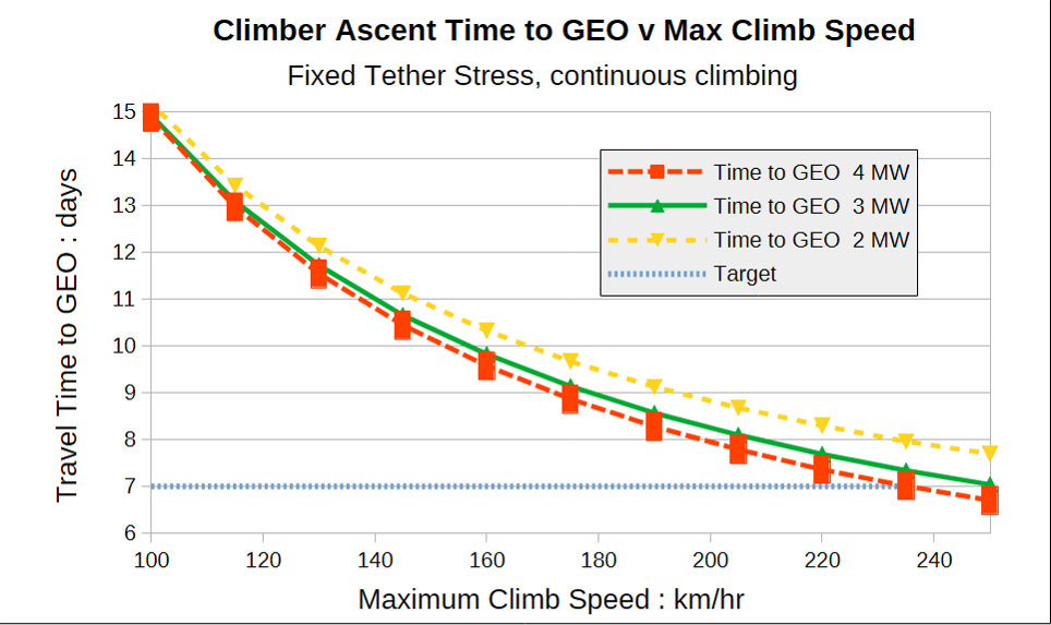
Figure 1: Climber Ascent Time (Earth to GEO) v. max speed & climber drive power, for 24hr climbing each day, fixed tether load and daily departures. Analysis: P. Robinson.
The plots are not linear as the climber reaches the speed limit earlier with lower speed limits and higher powers.
An important conclusion must be that the target ascent time of 7 days from Earth to GEO relies far more on the speed limit than the power.
3. Effect of Maximum Speed and Power on Climber Payload
Figure 1 does not show that closer climber spacing as speed and power falls requires a lower total climber mass to keep the same tether stress, meaning less payload can be carried. The payload change with power is shown in Figure 2 below. The 235 km/hr data was already presented in my earlier article [1], but a new dataset for 160 km/hr (100 mph) is now added.
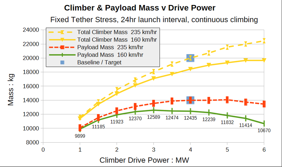
Figure 2: Total and Payload Mass v. Climber Power for 165 kph & 235 kph Maximum Climb Speed. 24hr climbing, fixed tether load, daily departures. Analysis: P. Robinson.
It can be seen that the lower maximum climb speed reduces the payload, but perhaps less expected is the reduction of the highest useful power from c. 4MW to c. 3MW. In more detail, the lower speed of 160 km/hr has a payload of 12,589 kg at 3 MW power, compared with 12,435 kg at 4 MW, a reduction of 1.2%. At the higher baseline speed of 235 km/hr there is a payload increase of 3.2% for the same power increase, yielding the target payload of 14,000 kg.
Figure 3 looks again at the effect of maximum speed, this time on payload for climb powers of 3 MW and 4 MW, showing a cross-over point at around 175 km/hr at which the payload is the same.
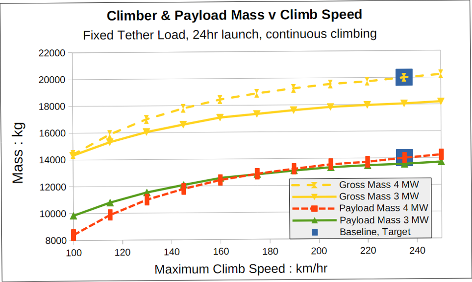
Figure 3: Total and Payload Mass v. Max Climb Speed for 3MW and 4MW power. 24hr climbing, fixed tether load, daily departures. Analysis: P. Robinson.
Given that even 160 km/hr may be significant engineering challenge I repeated this analysis with a lower power, yielding Figure 4 below. For clarity this now only presents the payload mass, with data for 2 MW in addition to the 3 MW and 4 MW results already shown in Figure 3.
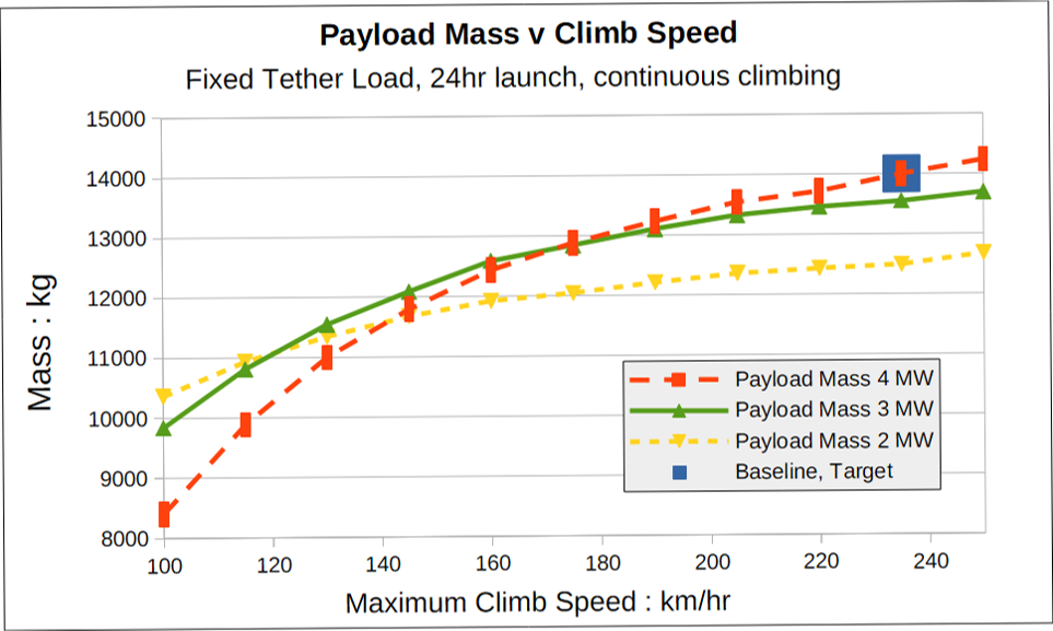
Figure 4: Payload Mass v. Max Climb Speed for 2MW, 3MW and 4MW power. 24hr climbing, fixed tether load, daily departures. (Note: discretisation errors result in some non-linearity at this enlarged Y-axis scale). Analysis: P. Robinson.
At 2 MW the payload falls less rapidly at lower speeds, but above 120 km/hr the higher powers are increasingly more capable.
A line plotted through the highest of the points at each speed of Figure 4 might be a useful representation of the impact of climb speed on payload regardless of the climb power.
4. Conclusions
1. The maximum climber speed is a key factor influencing the ascent time to GEO, but also significantly impacts the climber payload if the peak tether tensile force is held constant.
2. Early operational climbers should perhaps aim to have a maximum ascent speed of 160 km/hr, with a development “stretch” target of 235 km/hr to maximise payloads later.
Note, the payloads quoted in this article are for a fixed tether stress, per day. Higher masses can be raised by using a stronger tether, with payloads proportional to the tether mass for the same working stress. That means these conclusions on speed are equally valid for a 100-tonne “space train” or a 40-tonne cargo climber, assuming the same power/mass ratio and departure interval.
NEXT TIME: I will explore the effect of the Power/Mass Ratio, assumed so far to be constant at the value of the baseline climber design of 4 MW / 6 tonnes first defined in 2012 (or earlier).
5. References
[1] “Climber Motion Update: Power”, P. Robinson, August 2026 ISEC Newsletter Article.
[2] “Space Elevator Climber Dynamics Analysis and Climb Frequency Optimisation.”, P. Robinson, IAC2022 paper IAC-22,D4,3,8,x68299.
[3] “Powering the Space Elevator”, L. Bartoszek et al, ISEC 2026 Study Report.
ISEC Terminology
by Pete Swan
“Material Ranking”
For the last 15 years, ISEC has led the space elevator community toward understanding the strongest materials now and in the near future. Adrian Nixon has been our leader in addressing the attributes of those strong materials. The space community started with diamond thread (A. C. Clarke) and matured to real materials of carbon nanotubes (thanks to Brad Edwards, Bryan Laubsher, and team). Materials have matured towards a new category of “strongest,” i.e., 2-D single molecules with x-y layout. We have always listed our potential materials by strength, length, producibility, and availability. A new front runner has surfaced. Polycrystalline graphene is now leading the race. Please see article by Adrian in this month’s newsletter explaining further the “real” potential of this material (90+ GPa, 1,000 m at 2m/min produced in South Korea).
Tether Materials
by Adrian Nixon
Diamond Nanotubes
Dear Reader, you will recall that in the previous newsletter (June-July 2026) we explored the progress in creating diamond nanothreads (DNTs) [1]. The research for that article led us to discover a new material, diamond nanotubes. A representation is shown in Figure 1.
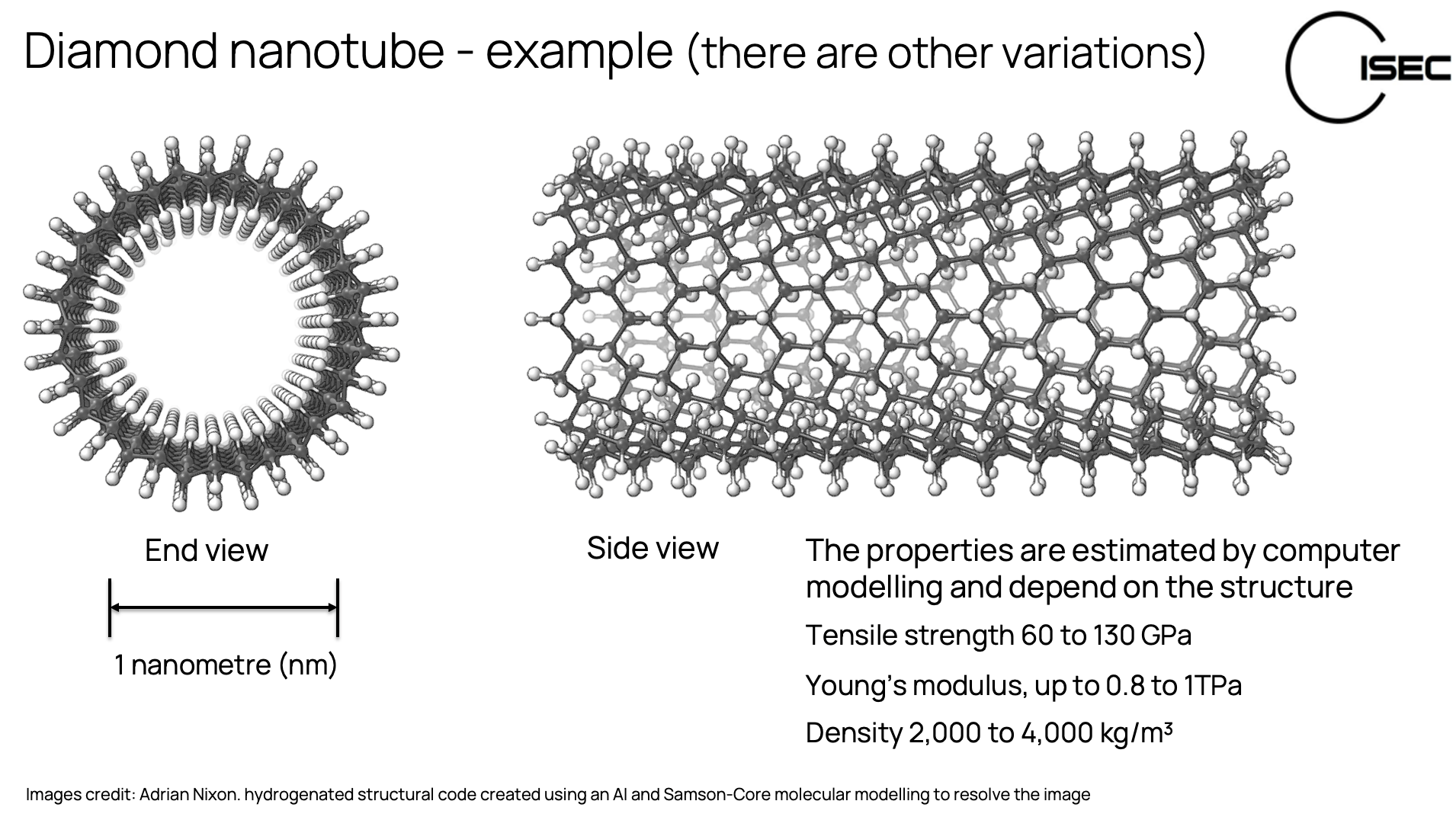
Figure 1. Example of a diamond nanotube.
Diamond nanotubes have similar strengths to the diamond nanothreads we discussed in the previous article. The values vary depending on the structures of various types of diamond nanotubes:
Tensile strength between 60 and 130 GPa
Young’s modulus 0.8 to 1TPa
Mass density 2 to 4 kg/m3
Diamond nanotubes may sound similar to carbon nanotubes; however, they are quite different. Diamond nanotubes have sp3 hybridised bonds where each carbon atom is bonded to four others except at the surfaces where hydrogens replace carbon atoms. Carbon nanotubes have sp2 hybridised bonds where each carbon atom is bonded to three others except at the tube ends and hydrogen terminates the structure. Figure 2 shows examples of the two structures.
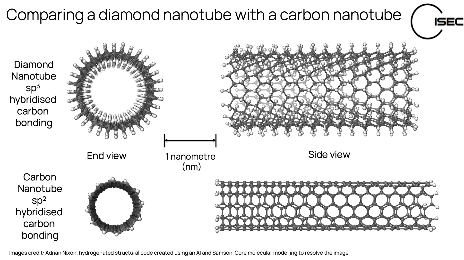
Figure 2. Example of a diamond nanotube and a carbon nanotube.
These illustrations are based on molecular modelling, using a computer to calculate and visualise the structure based on the known properties of carbon and hydrogen bonds.
In the 20th and early 21st century, the prevailing view of scientists was that tubular diamond structures were impossible due to the rigid nature of sp3 bonds (unlike flexible sp2 bonded carbon nanotubes). A search of the literature found very little work on diamond nanotubes until we came across a paper from 20 years ago that proved this view to be wrong…
We discovered that in 2004, a team at the Department of Materials Science and Engineering, National Tsing-Hua University in Taiwan, did actually make diamond nanotubes in the laboratory. They called these nano-scale diamond tubes (NDTs).
The paper titled "Formation of nano-scale tubular structure of single crystal diamond" [2], describes how the team formed vertically aligned nano-scale diamond tubes on the surface of polycrystalline diamond. They used a Microwave Plasma Enhanced Chemical Vapor Deposition (MPECVD) method and a feedstock gas containing 30% methane (CH4) and 70% hydrogen (H2) at a temperature of 200°C, for 2 hours.
They found that diamond nanodots started to grow on the diamond surface and these nucleated at grain boundary valleys. These nanodots coalesced into larger dots and circular coalescence created tubular nano-diamond structures.
The nano-diamond tubes were 3,000nm (3 µm) long with an outer diameter of 50-160nm and an inner diameter of 100nm. Electron diffraction analysis indicated that the nano-diamond tubes had a single crystal diamond structure.
In Summary
Work early this century, in 2004, proved that nano diamond tubes can be grown by a plasma enhanced chemical vapour deposition method. These NDTs were 3,000 nanometres long and approximately 100 nm wide. They were not tested for strength, but computer modelling estimates the tensile strength to be in the range of 60 to 130 GPa.
In theory these NDTs could be a tether quality material (if the density can be quantified). In practise much more work needs to be done to scale the length and speed of production. Extrapolating from the paper, the nano diamond tubes grew to three microns long in 2 hours. This means it would take roughly 76 years of continuous production to make one metre of material.
So, while nano diamond tubes do exist and can be made in the laboratory, they are more an academic research curiosity than a practical tether material for the moment.
References
1. Nixon, A. (2026) International Space Elevator Consortium Newsletter August International Space Elevator Consortium. [online] ISEC. Available at: https://www.isec.org/space-elevator-newsletter-2026-august/#tether
2. Chih, Y.K., Chen, C.H., Hwang, J., Lee, A.P. and Kou, C.S. (2004). Formation of nano-scale tubular structure of single crystal diamond. Diamond and Related Materials, 13(9), pp.1614–1617. doi:10.1016/j.diamond.2004.01.018.
Musical Corner
Three Space Elevator Songs By Dr. Donny “Rocker” Deever
ISEC is elated that Dr. Deever has created three songs representing his/our feelings towards space elevators. Poetry to music supporting:
“Green Road to Space”
“Send It Up (Bring the Price Down)”
"Build the Road (To Mars, Asteroids, and Far-off Stars)”
by Donny Rocker Deever & America 250 Band
Around the Web
Take a look at this New York Post article featuring ISEC Chief Architect Pete Swan: https://nypost.com/2026/08/31/science/first-space-elevator-a-66000-mile-cable-to-the-cosmos-closer-than-ever-before-as-scientists-make-breakthrough/ Two small clarifications: The article identifies Pete as ISEC President; he currently serves as ISEC’s Chief Architect. Additionally, the statement that a single layer of graphene can stop a .38-caliber bullet is a common misconception and is not accurate.
Enjoy this video from Isaac Arthur called "The First Space Elevator: Where Would We Build It?" https://www.youtube.com/watch?v=PS94bPJamRs
Upcoming Events:
Virtual ISEC Space Elevator Conference 2026
Sponsored by the International Space Elevator Consortium
https://www.isec.org/events/isec2026
Saturday, September 12th, through Sunday September 13th, 2026
77th International Astronautical Congress
Sponsored by the International Astronautical Federation (IAF)
https://www.iac2026.org/iac-2026
https://www.isec.org/events/77th-international-astronautical-congress
Theme: “The World Needs More Space”
October 5th through October 9th, 2026
Antalya, Turkey
International Space Development Conference 2026
Sponsored by the National Space Society
https://isdc.nss.org/
Thursday, May 27th, through Sunday, May 30th, 2027
Sheraton Gateway at LAX
Los Angeles, California, USA
78th International Astronautical Congress
Sponsored by the International Astronautical Federation (IAF)
https://www.isec.org/events/iac2027
Monday, September 27th through Friday, October 1, 2027
Poznań, Poland
79th International Astronautical Congress
September 1, 2028 through September 5, 2028
Samarkand, Uzbekistan
Contact Us:
Our website is www.isec.org.
You can find us on Facebook, X, Flickr, LinkedIn, Instagram, YouTube, Bluesky and Reddit.
Support us:
Sign up to be a member at: https://www.isec.org/membership
You can also give directly using the “Donate” link at the bottom of our website page.
Does your place of employment do matching funds for donations or volunteer time through Benevity? If so, you can make ISEC your recipient. Our 501(c)(3) number is 80-0302896.