International Space Elevator Consortium
October-November 2025 Newsletter
In this Issue:
Editor’s Note
Chief Architect’s Corner
ISEC Terminology
Tether Materials
Space Elevator Design Verification
Architecture Note #71
Around the Web
Upcoming Events
Contact Us
Editor’s Note
Dear Fellow Space Elevator Enthusiasts,
Thank you to those of you who were wondering what happened to the October newsletter. We could have published with the few articles we had, but decided to take a break and publish in November with a more robust Table of Contents. Thank you for your patience!
This month, we have started a new feature called "ISEC Terminology" to keep our readers informed of the terminologies we use and how we define them. We launch with the definition of "Modern-Day Space Elevators." It seems a good place to start!
Sandee Schaeffer
Newsletter Editor
Chief Architect’s Corner
by Pete Swan
Success at IAC-25
The beauty of the International Astronautical Congress each year is the “reach” we achieve across the global space community. They are right in front of us as we attend seminars, present our research, meet other space professionals, and enjoy the remarkable environment. Not only do we have exciting opportunities to broadcast progress of modern-day space elevators (MDSE) within the global space world, but we get to re-enforce, re-energize, and update our followers from around the world. Some of our successes this year were:
1) Visible participation within global conference: (a) dedicated session on Space Elevators (continuous since 2004), (b) 12 papers accepted (9 were given), and (c) two additional papers within two other sessions. If you are curious, papers and presentations have been posted on our website (isec.org/recent-publications)!
2) Shared formal dinner within the International Academy of Astronautics where everyone knows me as “Mr. Space Elevator”.
3) Attended two planning meetings for a global event – IPSPACE (working to include four SE presentations and maybe publish papers in a separate venue).
4) Attended significant meetings with the IAA/NSS/IAF 3-year study on Space Solar Power – resulting with the inclusion of Modern-Day Space Elevators in their remarkable final report (which is still in draft form).
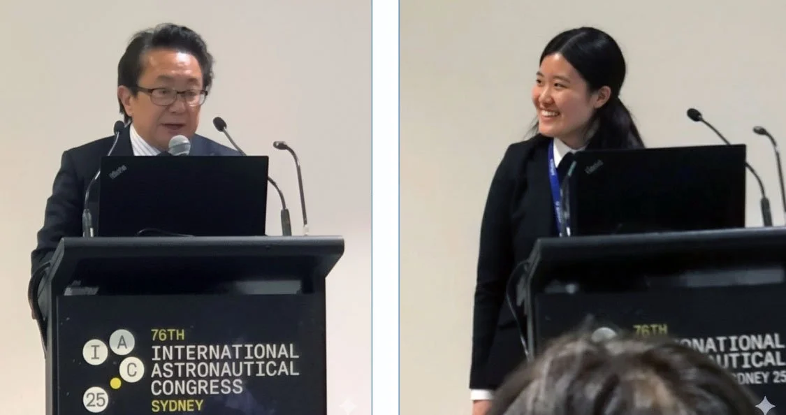
Yoji Ishikawa and Momoe Terata speaking at the IAC2025 Space Elevator session. Photo credit: M. Terata (processed by P. Robinson with enhancement by Gemini AI).
If you are interested in contributing to the future “reach out” activity through a research paper/presentation at an IAC, I would encourage submitting an abstract before 28 Feb. The next conference is in Turkey followed by Poland in 2027.
Thank you to all of you who helped prepare for this event and contributed to the research and advancing concepts.
ISEC Terminology
by Pete Swan
“Modern-Day Space Elevators”
“Modern-day space elevators” – use of this terminology confirms that we have moved into the 8th architecture for space elevators (see David Raitt’s discussions over the last few years) with the recognition that we are ready to enter engineering development with a material that will be out of the laboratory within 5 to 8 years. – Raitt, D., “Space Elevator Architectures,” Quest Magazine, Quest 28:1 2021.
Tether Materials
by Adrian Nixon
Mirror-Like Graphene Laminate Has Been Made in the Lab
Regular readers may recall that back in 2020 we predicted that a tether made from multilayer graphene (graphene laminate or graphene super laminate) would have a silvery metallic appearance. We went further and said that the material would have a mirror-like appearance [1]. Figure 1 shows a representation of the graphene laminate tether.
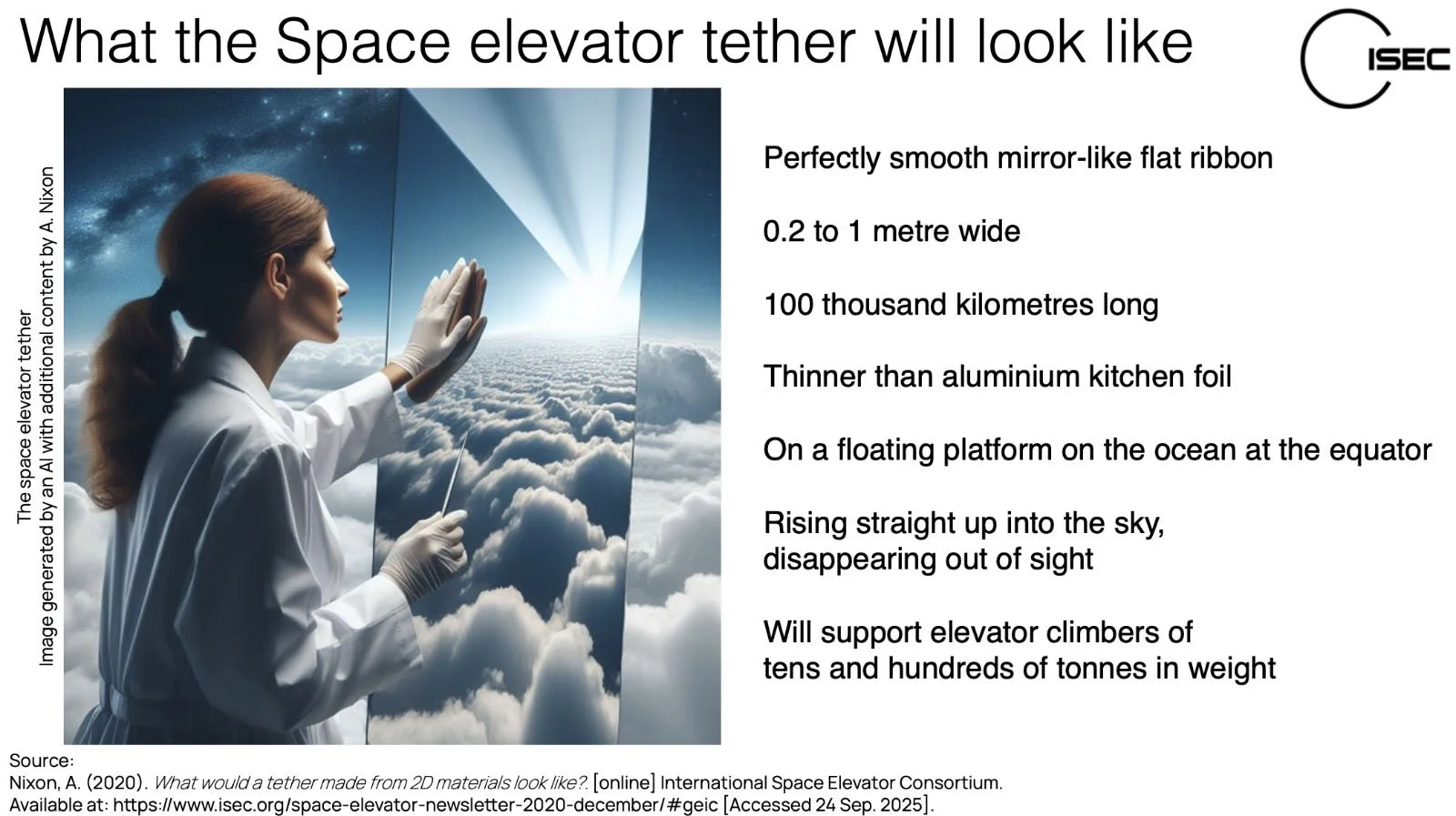
Fig 1. A space elevator tether made from graphene laminate or graphene super laminate.
This prediction might not seem controversial. However, consult an expert in the world of graphene, and they will tell you that graphene is a material made of one to ten atomically thin layers of sp2 hybridised carbon. Any more than ten layers and the material is graphite. This is enshrined in an international standard ISO/TS 80004-13:2017(en) [2].
Academic researchers like to use standard definitions. So, any material that is more than ten layers of graphene will be termed graphite when they report their work. However, large-area sheet graphene can be made at industrial scale, and we can now anticipate a new bulk material made from many tens of thousands of layers of graphene at scales of centimetres, metres, and even kilometre scale. This large-scale material will contain more than ten layers of graphene, but it will be completely different to graphite even though the technical term graphite could be used to describe the material. This is why we use the term graphene laminate and graphene super laminate to describe these new human-made materials. Figure 2 shows the difference between graphite, graphene, and graphene laminates.
Fig 2. Graphite, graphene and graphene laminates.
You will be familiar with graphite; it is commonly encountered as the stuff of pencils, a dull grey material, rather uninspiring and nothing like a mirror. So, why did we predict that graphene super laminate would be shiny and mirror-like?
Fig 3. Graphite, graphene and graphene super laminate reflectance.
Figure 3 shows our hypothesis for how light interacts with graphite and graphene powders and graphene super laminate. When incoming light interacts with the powder, the myriad nanoplates scatter light in different directions (diffuse reflectance); most of the incoming light is further scattered and absorbed by the bulk material. The net effect is that the material has a matte dark grey or black appearance. Graphene super laminate has a very smooth surface and while some of the incoming light is absorbed by the top few tens of layers, most of the light is reflected in a strong directional way giving a mirror-like appearance.
Until a few weeks ago, this was just a hypothesis. Then last month, a team at the Center for Multidimensional Carbon Materials (CMCM), Institute for Basic Science (IBS), and the Ulsan National Institute of Science and Technology (UNIST), Ulsan, in the Republic of Korea, led by Professor Rodney Ruoff published a new paper, Fig 4. [3].
Fig 4. Mirror-like graphene super laminate (single crystal graphite) made in the lab. Image credit: nature communications, Creative Commons Attribution 4.0 International licence (CC BY 4.0).
Professor Ruoff’s team reported they made large grains of graphite. They were able to test the strength of these domains and found the average fracture strength (tensile strength) to be 1.29 GPa. If these grains were single crystals of graphite, this would be graphene super laminate with a tensile strength of 130 GPa. The lower tensile strength means the graphite domains were probably closer to polycrystalline multilayer graphene (graphene laminate) with vacancy defects.
However, the key finding of the work was that the team was able to make graphene laminate domains at the millimetre scale and they were smooth and highly reflective with a mirror-like surface.
This is experimental work making graphene laminate in the laboratory proves the hypothesis we proposed five years ago that graphene laminate and super laminate will have a mirror-like appearance.
We now know that a space elevator tether made from graphene laminate will look like a highly polished, thin metal mirror.
References
1. Nixon, A. (2020). What would a tether made from 2D materials look like? [online] International Space Elevator Consortium. Available at: https://www.isec.org/space-elevator-newsletter-2020-december/#geic [Accessed 24 Sep. 2025].
2. Anon (2017). ISO/TS 80004-13:2017(en) Nanotechnologies — Vocabulary — Part 13: Graphene and related two-dimensional (2D) materials. [online] Available at: https://www.iso.org/obp/ui/#iso:std:iso:ts:80004:-13:ed-1:v1:en [Accessed 24 Sep. 2025].
3. Zhang, L., Wang, M., Jeon, D., Meng, Y., Lee, S.H., Choe, M., Li, Y., Wang, M., Lu, S.J., Lee, Z., Seong, W.K. and Ruoff, R.S. (2025). Synthesis and properties of mirror-like large-grain graphite films. Nature Communications, 16(1). doi: https://doi.org/10.1038/s41467-025-62227-6.
Space Elevator Design Verification
by Peter Robinson
Part 2: The Start of Design Verification Testing
1. Introduction
The first of these articles [1] discussed the variety of project management methodologies and the Technology Readiness Level (TRL) concept as used by NASA [2] and others, shown again in Figure 1 below.
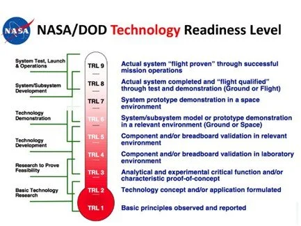
Figure 1: TRL Summary. Credit: NASA.
I described how the stages of a project Design Verification process will not usually align with TRL stages and would typically being much later in the project. I then proposed the following Design Verification Phases, broadly based on the TRL stages.
Phase 3 – The start of Design Verification, including virtual and real-world testing to confirm Design functionality.
Phase 4 – Further ground-based testing to optimise and refine design details.
Phase 5 – Initial space testing of materials and sub-systems.
Phase 6 – Space sub-system prototype verification testing.
Phase 7 – Space testing to verify integrated system operation.
Phase 8 – Assembly and qualification testing of first Earth Space Elevator.
Any future Space Elevator mega-project may well select a project management system which does not align with the above, but I will use them as a basis for these articles to suggest some of the potential work stages.
Phases 1 and 2 were covered in the first article [1]; what follows describes Phase 3. Key deliverables from this phase are presented in Figure 2 below, making use of the NASA TRL-3 definitions.
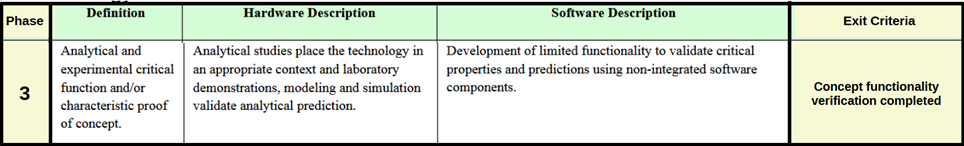
Figure 2: Proposed Design Phase Definitions (3). Credit: NASA, P. Robinson.
As before, I will concentrate on three key sub-systems, “Tether”, “Climber” and “Dynamics”, as defined in reference [1].
My presentation at the 2014 ISEC Conference [3] is perhaps also relevant; I gave an overview of project stages with a focus on simulation model validation. Figure 3 shows an early general slide, outlining my suggestions of what might be included in early project “Groundwork” (broadly aligned with what I am now describing as “Verification Phase 3”).

Figure 3: 2014 Project “Groundwork” Suggestion. Credit: P. Robinson.
2. Design Verification Phase 3: TETHER
2.1 Tether Strength
The selected tether material’s specific strength is critical for the entire project and must be demonstrated to reach the level necessary for the chosen Earth Space Elevator design. This strength must be measured on a sample size sufficient to represent a tether, for example with a thickness (or number of atomic layers) of a similar order of magnitude to that foreseen in the working tether concept.
2.2 Tether Production
The selected tether material must be produced in sufficient quantity to enable manufacture of test pieces to support other work, for example as outlined below. The sample requirements will be determined when testing details are finalised, but this may involve production of ribbon samples totalling many hundreds of metres in length.
The ribbon width, thickness, and quality may not need to match what is planned for a full-scale system, but it must be adequate to enable representative testing. If defects are present, then their root cause must be established and corrective process or other improvements identified.
2.3 Other Tether Properties
Ribbon samples must be extensively tested to determine all important properties, not merely the fundamental specific strength. Mechanical properties might include surface friction, shear strength, Poisson’s Ratio, impact resistance, fatigue life, resistance to tearing, and delamination, etc. Electrical and thermal properties must also be established. All properties would need to be assessed over a wide range of temperatures, stresses, and chemical/radiation environments.
Material testing would continue throughout the project as manufacturing methods are developed, these early “Phase 3” tests would be laboratory-based aimed at confirming the fundamental suitability of the chosen material and manufacturing process.
3. Design Verification Phase 3: CLIMBER
Outline concepts for all climber components will be produced during Phase 2, but those must be converted to detailed designs for prototype sub-system functionality testing during Phase 3.
3.1 Concept Verification: Scale
A key decision that must be taken before the start of the detailed design for “Mark 1” prototype climber systems is the scale and possible modularity. The reason for this assertion is that any given tether will be capable of only supporting a given weight of climber(s), with the maximum gross mass of each climber depending on the number of climbers on the tether and their altitude distribution. For at least the last 25 years the climber concept has been for a single daily climber launch, but my 2022 paper [4] confirmed earlier work by Shelef [5] in concluding that multiple daily launches of less massive climbers would maximise the gross launch mass capacity of any tether system.
Multiple daily launches mean each climber must be smaller (for a given tether strength), fundamentally impacting the design. If these smaller climbers were modular, there would be options for multiple daily launches of divisible cargo (i.e. fuel) carried on single modules, whilst indivisible cargo (i.e. a large space telescope or spacecraft) could be carried on multiple modules combined in a train to create a single climber up to a size limited by the tether tensile strength.
A modular concept would result in significant economies of scale in production, with further benefits to the verification test programme. Smaller and less costly modules would mean more prototypes for the same budget, enabling quicker and more thorough development, and accelerate the reliability growth process.
(The above may appear to be a digression from the topic of Verification Testing, but the climber scale is a critical decision that must be finalised at or before this “Phase 3” of the project.)
3.2 Climber/Tether Interface
The 2023 ISEC Study [6], and other work elsewhere such as the IAC paper, “Development of Hybrid Space Elevator Climber with Continuously Adjustable Roller Drive Arrangement”, concludes that some form of friction drive system will be used in early SE climbers [7]. The verification work required for the project “Phase 3” might include tests of a prototype wheel/roller drive system to the scale of the production-intent climber on a tether of the intended material produced as described in 2.2 above. These tests might be on an extended vertical length of tether, or perhaps on a continuous looped tether in a vacuum chamber as already being undertaken at a smaller scale in Japan [7].
This work would assess critical performance and durability aspects of the climber drive system and in doing such, perhaps evaluating alternate wheel materials and establishing friction, durability, thermal behaviour, and other parameters such as tether wrinkling. This work would be done over a wide range of speed and load conditions to simulate conditions at all altitudes from Earth to GEO.
3.3 Motor Selection
The work described in 3.2 above might not at first include a representative drive motor. The motors for an SE climber will have a number of special requirements which may dictate a new or unique design. These requirements include continuous in-vacuum operation (meaning they cannot be air-cooled), a high stall torque, a high operating speed range, a high power/weight ratio and maximised efficiency (to minimise cooling requirements).
Prototype motors must be procured and extensively tested in this verification phase, confirming a path towards meeting performance requirements across the required speed and load range.
3.4 Power Supply
A number of climber power supply systems are still being considered, but a decision must be made before the start of verification “Phase 3” to permit work to proceed with prototype system procurement, test, and development. An on-board power supply appears unlikely, meaning that power must be supplied from some external source. At present, the options being advocated or investigated include solar power, beamed laser or microwave power from space or the surface, or transmission along the tether itself.
The exit criteria for this phase of work might include demonstration of a full-scale power supply system in preparation for longer-term environmental, performance, durability, and reliability evaluation. The system mass may not be as low as required at this stage.
3.5 Other Systems
There are other essential or optional climber systems/components, including a chassis, one or more control/communication systems, a cooling system, a steering mechanism, some form of tether “anti-wrinkle” system (if needed), a parking or emergency brake, an emergency “eject” mechanism, and more. Concepts for all these must be finalised and designed, followed by prototype sub-system tests.
3.6 Prototype Assembly and Test
The exit criteria for “Phase 3” of the Climber sub-project might be completion of individual full-scale prototype sub-system tests, completion of a Critical Design Review (or some equivalent project management Gateway), and perhaps the assembly of the first complete functional prototype climber.
3.7 Climber Verification: Summary
The above is intended to give some indication of the scale and scope of the Climber design verification and development task. The climber will be a technically complex vehicle with challenging mass, performance, and cost targets.
The work will require a significant engineering team, perhaps numbering many hundreds, perhaps comparable to that of a Formula 1 racing car team. Multiple design iterations are likely during this phase of the verification process, yielding a probable timescale of years rather than months.
4. Design Verification Phase 3: DYNAMICS
4.1 Simulation, Metrology and Control
Another slide from my 2014 conference presentation broadly summarises the validation of the simulation code and making use of metrology systems to gather the required data to confirm model accuracy (see Figure 4 below). (Note: the Phases mentioned in this early work do not align with the Phases of these 2024 articles.)
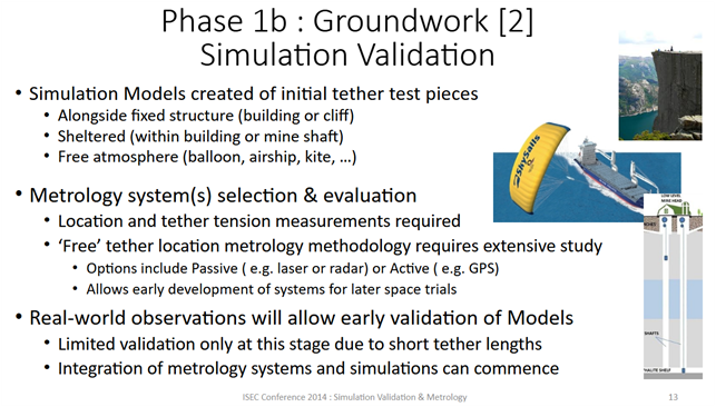
Figure 4: 2014 “Simulation Validation” Overview. Credit: P. Robinson.
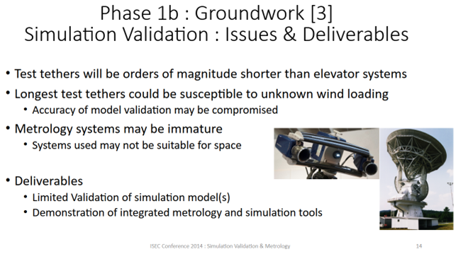
This slide highlights that any simulation code must be validated against real-world data, and in the case of tether simulation this provides an opportunity to assess the functionality and software integration of positional and tensile metrology systems. This assessment would be limited by the small scale of ground-based tethers in comparison to an SE tether, as outlined in another slide from 2014 shown in Figure 5 below.
Not mentioned in the above slides is the need for control mechanisms to induce tether motion to avoid objects in space. Early proposals were for movement of the entire Earth Port, based on the assumption that it would be a floating platform, but other options include tether winching at the Earth-Port Reel-In-Reel-Out (RIRO) winch, or thrusters on climbers or elsewhere on the tether. Initially the simulation code could be used to assess the probable effectiveness of these and other options, but the real-time control system needed to generate the commands to avoid multiple satellites, orbital debris, etc. would be computationally extremely complex.
The complexity of the chosen tether control system is likely to be generically described as “AI”. I will not attempt to predict the details of such a system at this stage, given my lack of specialist knowledge and the ongoing rapid advancements in this field, but I will suggest that some system with basic control functionality will need to be evaluated as part of “Phase 3” verification.
4.2 RIRO Definition
An important aspect of tether tension and dynamic control is the RIRO system, located at the Earth Port or perhaps elsewhere. On the Earth’s surface this could be a relatively simple winch system, but I will suggest that detailed designs should be produced and evaluated (at least virtually) as part of “Phase 3” verification.
If RIRO systems are needed in space, then designs will be more complex, with the mass and power supply being important considerations. The need for such systems must be established in “Phase 3” by analysis using the Simulation and Control systems discussed above.
4.3 Dynamics Verification Summary
The issue of orbital traffic and debris is frequently raised as a key objection to the Space Elevator concept. Debris clearance and satellite tagging (or transponders) would reduce the problem, but active control of the tether dynamics will be needed to avoid every single potential collision. This means the tether control systems outlined in 4.1 are critical aspects of the project, making it essential that a robust and totally reliable solution is devised and verified.
5. Summary
The detail in the three preceding sections is not intended to be comprehensive but perhaps gives an indication of the scope of some technical elements of the early practical Phase of the Space Elevator Mega-Project. A significant engineering team will be needed to move the project forward, requiring major financial backing and other support resources typical of any major business enterprise.
I have outlined possible further Phases in Section 1 above and will suggest example engineering content of each in subsequent articles, continuing with Phase 4 next time.
6. REFERENCES
[1] Peter Robinson: September-2025 ISEC Newsletter Article, “Introduction, Technology Readiness and Design Verification”
[2] Technology Readiness Levels - NASA
[3] Space Elevator Validation and Metrology Requirements”, P. Robinson. Presentation at August-2014 ISEC Conference, Seattle. (Available to ISEC members in Zotero library)
[4] “Space Elevator Climber Dynamics Analysis and Climb Frequency Optimisation.”, P. Robinson, IAC2022 paper IAC-22,D4,3,8,x68299: https://www.isec.org/s/ISEC-2022-IAC-space-elevator-climber-dynamics-paper.pdf
[5] “Space Elevator Power System Analysis and Optimization”, B. Shelef, Sept-2012. (No longer available on-line; available to ISEC members in Zotero library).
[6] 2023 ISEC Study “The Climber-Tether Interface of the Space Elevator”
[7] “Development of Hybrid Space Elevator Climber with Continuously Adjustable Roller Drive Arrangement”, M. Terata et all, IAC paper IAC-25,D4,3,4,x95919 presented 30-Sep-25 (available to ISEC members in Zotero library)
Architecture Note #71
Ensuring ISEC is Recognized as the Leader through Active “Reach Out” Program
The Chief Architect just placed AN #71 on our website with a goal of ensuring all ISEC members realize there is a tremendously important role that each of you play. We must have the creative, informative, and research activities of ISEC distributed across the globe. Our goal is to stimulate thoughts and actions to support the idea that the Modern-Day Space Elevator is critical to the health of the Earth and the advancement of the human activities off planet. We have a splendid monthly newsletter that reaches many; however, our many various approaches have not yet led to breakout activities where we could initiate our needed revolution. Please review the Architecture Note #71 and suggest “ways to improve” our Reach Out program. Here is the breakout that I see reference our ability to reach beyond readers of the Newsletter.
+ Research Study Reports: Our 16 completed studies (with three on-going) continue to supplement our past activities folding together design arenas with innovative results amazing our readers and researchers.
+ Publish: Our efforts to publish in significant journals and magazines have been very successful over the years. Recently, the British Interplanetary Society supported us beautifully.
+ Space Elevator Conferences: ISEC conducts a yearly conference with speakers from across the space elevator community. This last conference (2025) was virtual and very successful.
+ Body of Knowledge on Modern-Day Space Elevators: ISEC has been keeping records of all the work accomplished surrounding space elevators.
+ Newsletter: We have a splendid monthly newsletter that reaches many.
+ Social media posting: We all recognize that the world of communications has become several levels more puzzling as the social media platforms have multiplied.
+ Student Involvement: As we have had international student involvement since the beginning, we should recognize their successes and their global reach. We have several efforts working with students.
+ National Space Society: ISEC has actively joined NSS in their yearly International Space Development Conferences (ISDC). Over the last few years, we have done very well and passed the word to their students and young professionals.
+ Global Space: Participating with the global space community to ensure we stand up as ISEC participates and supports their activities. The biggest opportunity is at the International Astronautics Federation’s yearly Congress.
Also recently added to the Architect’s Notes on our website: https://www.isec.org/architects-notes
+ #69: Modern-Day Space Elevator to Enable Planetary Defense
and
+ #70: Space Solar Power enabled by Modern-Day Space Elevators
Around the Web
Dennis Wright gave a “What is a Space Elevator” presentation at the WSPEC Virtual Workshop:
https://www.youtube.com/watch?v=8dYzUV0igT4
Larry Bartoszek gave a talk on bringing asteroid mining material down using the space elevator at the NSS Space Forum on Zoom that took place on November 13.
Upcoming Events:
Manchester Lit & Phil
Sponsored by Manchester Lit & Phil
https://www.manlitphil.ac.uk/events/the-space-elevator/
Wednesday, November 19th, 2025
The Space Elevator: Manchester, Graphene and a Bridge to the Stars. Presented by Adrian Nixon and Rob Whieldon
Lecture Theater, Renold Innovation Hub
International Space Development Conference 2026
Sponsored by the National Space Society
https://www.isec.org/events/isdc2026
Thursday, June 4th, through Sunday, June 7th, 2026
Space Elevator Session, Saturday, June 6th
Hilton McLean Tysons Corner
77th International Astronautical Congress
Sponsored by the International Astronautical Federation (IAF)
https://iac2026antalya.com/
Theme: “The World Needs More Space”
Proposed Dates: October 5th through October 9th, 2026
Antalya, Turkey
Contact Us:
Our website is www.isec.org.
You can find us on Facebook, X, Flickr, LinkedIn, Instagram, YouTube, Mastodon, Threads, Bluesky and Reddit.
Support us:
Sign up to be a member at: https://www.isec.org/membership
You can also give directly using the “Donate” link at the bottom of our website page.
Does your place of employment do matching funds for donations or volunteer time through Benevity? If so, you can make ISEC your recipient. Our 501(c)(3) number is 80-0302896.